


Z31 Exhaust Gas Temperature Sensor (California Models)
The exhaust gas temperature sensor is used on California-model Z31s only. It sits in the EGR system and lets the ECU confirm that the EGR valve is actually opening. When the EGR valve opens, hot exhaust gas flows past the sensor, its temperature rises, and its signal to the ECU drops. If the ECU doesn't see that change, it can flag the EGR system.
The sensor is a thermistor: its resistance decreases as temperature increases. It's not the same part as the exhaust gas (O2) sensor, which measures oxygen. See the O2 sensor page for that one.
Federal (non-California) cars don't have this sensor. ECU pin 30 is unused on them, and code 35 isn't available.
Specifications
| Used on | California models only (VG30E and VG30ET) |
| Trouble code | 35, exhaust gas temperature circuit (California only) |
| Signal wire | OR (orange) to ECU terminal 30 |
| Ground wire | B (black), shared with ECU terminal 26 ground |
| Harness connector | 39F |
| Resistance at 100°C (212°F) | 85.3 ± 8.53 kΩ |
| Signal at about 2,000 rpm, EGR closed | 1.0–2.0 V |
| Signal at about 2,000 rpm, EGR open | 0–1.0 V |
| Tightening torque | 15–25 N·m (1.5–2.5 kg-m, 11–18 ft-lb) |
Circuit
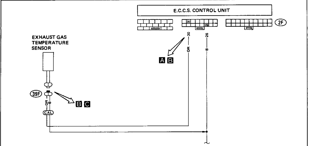
The ECU is behind the passenger-side kick panel. The connector letters A–C in the diagram match the test steps below.
Common Problems
- Code 35 stored in the ECU
- Code 32 (EGR function), since the ECU uses this sensor to check the EGR system. A stuck or clogged EGR valve, a bad EGR control solenoid or a cracked vacuum hose can set it even when the sensor is fine.
- Corroded connector or broken wires from exhaust heat
- On California cars, a lit check engine light and a failed emissions inspection
Troubleshooting
Before You Start
- Pull the ECU out from behind the passenger-side kick panel so you can reach its terminals.
- Disconnect the vacuum hose from the EGR control valve and connect a hand vacuum pump to the valve.
- Warm up the engine fully.
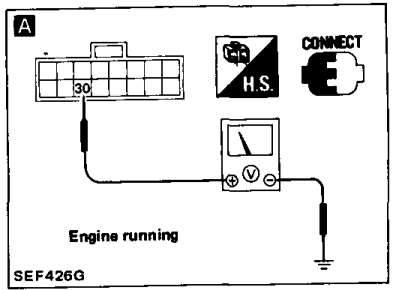
A. Check the Input Signal
- Start the engine and warm it up.
- Hold the engine at about 2,000 rpm.
- Check the voltage between ECU terminal 30 and ground:
| Condition | Voltage |
|---|---|
| No vacuum applied to the EGR control valve | 1.0–2.0 V |
| Vacuum applied to the EGR control valve | 0–1.0 V |
Applying full vacuum with the hand pump may stall the engine.
If the voltage is right, the circuit is good. If not, go to step B.
B. Check the Harness Between the ECU and Sensor
- Stop the engine.
- Disconnect the ECU 16-pin connector.
- Disconnect the exhaust gas temperature sensor connector.
- Check continuity between ECU terminal 30 and terminal (a) of the sensor connector. There should be continuity.
If not, check the middle harness connector, and repair or replace the harness as needed.
C. Check the Ground Circuit
Check continuity between terminal (b) of the sensor connector and ground. Resistance should be about 0 Ω. If not, check the middle harness connector and repair or replace the harness.
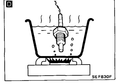
D. Check the Sensor
- Remove the exhaust gas temperature sensor.
- Heat the tip in water and watch the resistance. It should decrease as the temperature rises.
- At 100°C (212°F), boiling water, the resistance should be 85.3 ± 8.53 kΩ (about 76.8–93.8 kΩ).
If it's out of spec, replace the sensor and tighten it to 15–25 N·m (11–18 ft-lb).
After the Repair
- Reinstall everything you removed.
- Erase the self-diagnosis memory.
- Take a test drive, then run self-diagnosis Mode III again. See Z31 ECU Codes.
- If the code comes back, check the ECU pin terminals and the ECU harness connector for damage or poor contact.
Warning: do this work at your own risk. We are not responsible for any problems or damage caused by your own work.
Related Pages
Sources Used
- 1988 Nissan 300ZX Factory Service Manual, section EF & EC: Exhaust Gas Temperature Sensor (EF & EC-108 to 110) and Self-Diagnosis display code table (EF & EC-66)
- 1984-1988 Nissan 300ZX Factory Service Manual