
Z31 ECU Diagnostics
The ECU has a self-diagnostic mode which will allow you to read fault codes for major sensors.
The self-diagnostic system determines malfunctions of signals which provide data to the ECU. The malfunctions may not be only E.C.C.S component malfunctions, but may also be poor contact of the connectors, Shorted or open circuit of the harnesses and malfunctions of the transit relays and diodes. Some malfunctions are stored in the ECU and others are not. A malfunction is displayed by the red and green LEDs which are located in the control unit. Self diagnosis is performed when the self-diagnosis selector is in the on position.
The ECU is located in the right side of the passenger foot well behind the kick panel. The image below shows the location
1984-1987 Model Diagnosis
- Unhook the ECU from its bracket in the Right side of the passenger footwell (but leave it plugged into the ECU loom) and locate the mode selector (a small screw on one side).
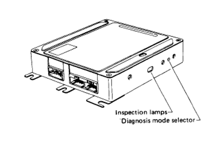
- Turn the ignition on - LED lamps viewed through the side window alongside the selector screw should be on.
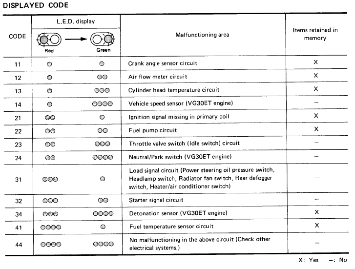
- Turn screw clockwise and LEDs will flash - red LED counts "tens", green LED counts "ones", e.g. one red flash followed by three green flashes = code 13.
- Write down the codes displayed (they will recycle, so don't worry if you miss one).
- Depress and release accelerator pedal.
- Shift transmission selector through each gear in turn, return to neutral.
- Start engine (if possible).
- Drive forwards at at least 6mph.
- Turn air-con on and off (if fitted).
- If all is well (and you have air-con that works! then code 44 will be displayed. If all is well and you do not have air-con, then 31 will be displayed.
Any other codes should be covered by the following list and, if still displayed, indicate a fault in that system:
- Unhook the ECU from its bracket in the left of the passenger foot well (but leave it plugged into the ECU loom) and locate the mode selector (a small screw on one side).
- Turn the ignition switch to the on position. Turn the diagnostic mode selector on the ECU fully clockwise and wait until the inspection lamps flash. Count the number of flashes to find out the mode you are in, then turn the diagnostic mode selector to fully counterclockwise.
- When the ignition switch os turned off during the diagnosis, in each mode, and turned back on again after the power has dropped off completely, the diagnosis will automatically return to mode I.
- On on California models, the check engine light will come on when the ignition switch is turned on or in mode I when the emission system malfunctions with the motor running.
- Malfunctions related to fuel and emission control systems can be diagnosed using the self diagnostic codes from mode II
- To start the diagnostic procedure, Start the engine and warm it up to normal operation temperature. Turn the Diagnostic mode selector fully clockwise. After the inspection lamps have flashed 3 times, turn the diagnostic mode selector fully counterclockwise. The ECU is now in mode III. Check the trouble code chart for the problem.
1988-1989 Model Diagnosis
| Trouble Code | Circuit or System | Possible Cause |
Code 11 (1 red flash, 1 green flash) |
Crank Angle sensor/circuit |
Faulty Crank Angle sensor/circuit |
Code 12 (1 red flash, 2 green flashes) |
Air Flow Meter/Circuit |
The Air flow meter source or ground circuit(s) may be shorted or open. Check the AFM |
Code 13 (1 red flash, 3 green flashes) |
CHTS Cylinder Head Temperature Sensor |
The sensor source or ground circuit(s) may be shorted or open. Check the CHTS sensor/circuit |
Code 14 (1 red flash, 4 green flashes) |
Vehicle Speed Sensor |
The Vehicle Speed Sensor circuit(s) is open. |
Code 21 (2 red flashes, 1 green flash) |
Ignition Signal |
The Ignition signal in the primary circuit is not entered during engine cranking or running. |
Code 22 (2 red flashes, 2 green flashes) |
Fuel pump circuit |
The Fuel circuit is open or shorted |
Code 23 (2 red flashes, 3 green flashes) |
Idle Switch circuit |
The Idle Switch signal circuit is open |
Code 31 (3 red flashes, 1 green flash) |
ECU Control Unit |
The ECU input signal is beyond “Normal” range. Replace ECU |
Code 32* (3 red flashes, 2 green flashes) |
EGR Function |
The ECG control Valve does not operate |
Code 33 (3 red flashes, 3 green flashes) |
Exhaust Gas Sensor |
The Exhaust Gas Sensor circuit is open |
Code 34 (3 red flashes, 4 green flashes) |
Detonation Sensor (turbo only) |
The Detonation Sensor may be shorted or open. |
Code 35* (3 red flashes, 5 green flashes) |
Exhaust Gas Temperature Circuit |
The Exhaust Gas Temperature Circuit may be shorted or open. |
Code 42 (4 red flashes, 2 green flashes) |
Fuel Temperature Sensor ** |
The Fuel Temperature Sensor may be shorted or open. |
Code 43* (4 red flashes, 3 green flashes) |
Throttle Sensor |
The Throttle Sensor may be shorted or open. |
Code 45* (4 red flashes, 5 green flashes) |
Injector leak |
An Injector(s) is/are leaking. Check and replace Injector(s) |
Code 55 (5 red flashes, 5 green flashes) |
No Malfunction |
Normal Operation |
- *California Models Only
- ** Code 41 for 1987 models