
S130 Fuse and Relay Locations
Your basic electrical circuit consists of an electrical component and its associated switches, motors, relays and such as well as the necessary wires and connectors to connect the component to the battery and the chassis. If you plan on troubleshooting any electrical circuit, it is highly advisable to locate a copy of the wiring diagram appropriate to what you're working on and examine it carefully, since you may be able to eliminate certain potential causes of your problem if certain components on that circuit are functioning properly.
If several components or circuits fail simultaneously, there's a chance that your problem could be related to a fuse or the ground connection, since there can be multiple circuits routed to the same fuses and grounds.
Component failure can also be caused by the simplest of electrical problems, such as a loose or corroded connection, blown fuses, or melted fusible links. You can save yourself plenty of time and colorful language by checking the condition of wires, connectors and fuses before tearing everything apart.
If all else fails and you need to break out the testing equipment, you're going to want to have a circuit tester or voltmeter, a continuity tester, and a jumper wire handy to bypass electrical components. It would be advisable to check the wiring diagrams before attempting to use any of this testing equipment in order to determine the necessary connection points for troubleshooting.
If a circuit is not functioning properly, you may want to perform a voltage test on it. Connect one lead of your trusty circuit tester to a known good ground, and the other to a connector in the malfunctioning circuit, as close as possible to the battery or nearest fuse. If you are getting voltage to this point, then that part of the circuit is not the culprit and you need to continue on in the same manner. Should you find a point where there is no voltage, then you know that the problem lies between that point and where you had last had a good test. Oftentimes the problem can be caused by a loose connection, and it is prudent to remember that some circuits will only show voltage readings when the ignition is in the Accessory or On position.
To check for shorts in a circuit, remove the corresponding fuse and connect a test light in its place in the fuse terminals. There should be no load in the circuit. Jiggle the wiring harness back and forth; if the test light lights up, then there is a short to ground somewhere nearby, possibly where some insulation has been eroded off of a wire. You can also use this method to test other parts of the same circuit, like the switch.
If it seems likely that a component may not be properly grounded, disconnect the battery and connect one lead of a continuity tester to a ground you know to be good. Connect the other lead to the wire or ground in question, and observe the bulb. If the bulb goes on, your ground is good. If the bulb remains unlit, you have a bad ground.
To check that electricity is flowing properly through a given circuit, perform a continuity test. Disconnect the battery and connect one lead of the continuity tester to one end of the circuit in question, and the other lead to the opposite end. If the bulb goes on, your circuit is allowing electricity to flow properly. Various electrical circuits have relays in the circuit. Relays keep heavy electrical loads from important contact points. They are located in various places in the car. (See Below)
In the S130 there are two types of fuse box configurations. The Early modes from 1979 to 81 used glass type fuses and from 82 to 83 blade type fuses are used.


The early style fuse boxes are prone to the fuse holders corroding and the holders breaking. Below is the Layout of the fuse boxes and what each fuse controls.
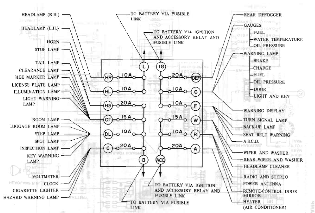
1979 Fuse box layout, Click to open larger.

1980 and 1981 Fuse box layout, Click to open larger.

1982 Fuse box layout, Click to open larger.

1983 Fuse box layout, Click to open larger.
Relay Locations
In the S130 the Relays are scattered throughout the car. The images below show where each relay is located.
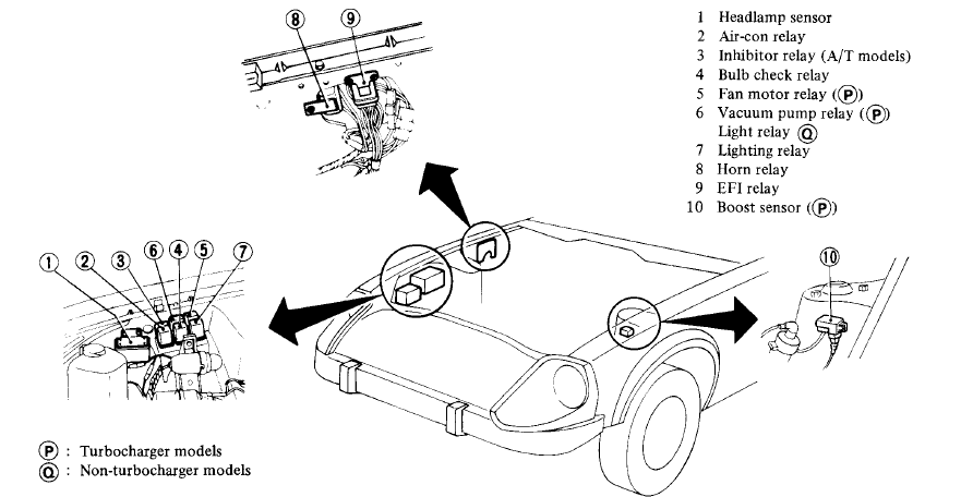
Click for larger view
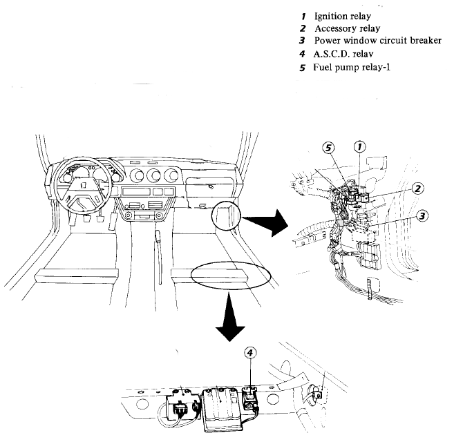
Click for larger view
Sources used on this page:
- 1979-1983 Nissan 280ZX Factory Service Manual
- s130 parts Fiche