
XenonZcar.com - S130 Automatic To Manual Climate Control Swap
- Section 1 Introduction
- Section 2. Dashboard Removal
- 2.1. Tools and Supplies Needed
- 2.2. Preparation
- 2.3. Steering Wheel Removal
- 2.4. Dash Removal
- Description
- Remove or not and further explanation
- Remove or not and further explanation
- Figure 4-3 Some Actual Parts to be Removed
-
Figure 4-4 Actual Auto Control Parts After Removal
- 5.1 Heater Unit Removal
- Section 6 Engine Modifications
- Section 7 Blower Unit and Vacuum Tank Modifications, Vacuum Hose Routing
- 7.2 Vacuum Tank Modification
-
Section 8 Installation, Testing and Checkout
Section 1 Introduction
The following document provides the necessary steps to modify a 1979 – 1983 280ZX Climate Control System from Automatic to Manual.
The Automatic Climate Control (ACC) and the Manual Climate Control (MCC) will be known as the auto and manual control throughout this procedure.
Most of the components that are part of the auto control can be reused for manual control with the exception of the following:
- a. Control unit attached to the front of the heater unit
- b. Water cock valve attached to the heater unit
- c. Heater hoses plus two fittings for the heater hoses (located in engine compartment)
- d. Wiring harness leading from the control unit to the blower
The modification requires the removal of the heater unit from behind the dash. In order to remove the heater unit, the dash must first be removed and the supporting bar removed from in front of the heater unit.
The entire removal, modifications and re-installation can be performed in about one weekend if all parts are on hand.
This procedure is written as a detailed guide for someone who is not familiar with the dash removal procedure or has never worked on the heater/AC system. Those that have experience please excuse the detail and use whatever information is needed.
Section 2. Dashboard Removal
2.1. Tools and Supplies NeededTools:
- • Two or three sizes of Phillips screwdrivers
- • Standard screwdrivers for possible hose clamps
- • 22 mm metric socket (for steering wheel nut)
- • 10 mm socket
- • 10 mm open end or box end wrench
- • 12 mm socket
- • Ratchet set for sockets with various length extensions
- • Sharp knife or razor blade
- •
Supplies:
- • Heater hose 5/8” ID X 7/8” OD
- • Vacuum hose 3/32” ID X 7/32” OD
- • Silicon lube (spray)
- • Foam insulation, strip – 1/2” width X 3/8” thick
- • Anti-freeze
2.2. Preparation
1. Drain the coolant from the radiator. With the engine on and heater in the heat mode, run the engine for a short time to drain the coolant from the heater core.
2. Disconnect the negative lead from the battery.
3. Be prepared to label the wire connectors and/or wire leads as you disconnect them.
4. Save and label each units’ or components’ mounting screws in a separate envelop.
2.3. Steering Wheel Removal
1. Remove the horn pad from the center of the steering wheel. The pad is a rubberized material that just slips off the steering wheel center section (no screws). DO NOT remove the horn actuation mechanism (just underneath the pad).
2. Remove the steering wheel nut using a 22 mm socket.
3. Pull the wheel off the shaft. Some times this requires a steering wheel puller but usually it can be loosened by bumping one side of the wheel while pulling up, away from the shaft, rocking the wheel from side to side.
Note the facing punch marks on the end of the shaft and the wheel hub. These marks must be aligned when re-installing.
2.4. Dash Removal
1. After removing the steering wheel from 3. above, remove the steering column shell cover (which covers the combination switch). There are eight screws accessed from below. The shell is split in half and separates after the screws are removed.
2. Remove the combination switch (which is the combination of turn signals/lights on the left and windshield washer/wipers on the right). This switch is removed by loosening the screw on the lower right side (back) and slipping the switch off the shaft.
Note the square pin on the switch and square hole on the shaft for re-alignment when re-installed.
3. Remove the radio panel lower covers. These are located underneath the dash on the right and left sides. For the left side disconnect the two wires from the entrance light and the two vacuum hoses from the vacuum control knob (for manual climate control cars only). For the right side disconnect the two wires from the entrance light.
4. Remove the instrument panel bracket covers. These are located on the left and right sides of the radio panel. Once these are removed you can see the bolts holding the radio panel.
5. Remove the radio and radio panel. Disconnect the radio antennae lead and the radio wires from the unit.
6. Remove the instrument center ventilator. This is the unit the surrounds the heater/AC control panel and the center dash vents.
7. Remove the two heater control unit securing screws from the support beam.
8. Disconnect the speedometer cable at the intermediate connector.
9. Remove the instrument panel (dashboard) upper plugs, which hide the securing screws. Remove the four screws. These are at the base of the windshield.
10. Remove the four lower securing bolts for the overall dash component.
11. Disconnect any instrument panel wiring connectors and label as necessary.
12. Pull the instrument panel (dashboard) out horizontally while lifting the heater control slightly to clear.
Note this step is best done by two persons for ease of removal.
The dash is now out and the heater unit, the air conditioner evaporator, and the blower are all visible. See Figure 2-1 for a view of the dash area without the dashboard.
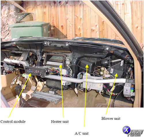
Figure 2-1
Dash Area After Removal
Blower unit
Control module
Heater unit
A/C unit
Section 3 Parts Needed for Modifications
1. The heater/AC control unit attached to the heater unit. This unit contains the vacuum control switch, the blower on/off and speed control switch and a micro switch for on/off control of the A/C unit. In addition the control unit has a small light and a control cable for actuation of the water cock.
If you get the unit from a wrecking yard it may be advantageous to purchase some new components such as:
a. switch/rheostat (recommended)
b. lamp (recommended)
c. micro switch (test for actuation)
You definitely need to check the lamp with a 12V source. Most of these components are next to impossible to replace once installed without removing the dash again.
2. The heater water cock. This component contains the heater water inlet valve and a controlling coil of copper tubing. It also has a mechanical link or interconnect with the air mix door of the heater.
3. The air mix door interlock rod, rod set screw and attachment to the air mix door shaft.
4. The heater hose inlet and outlet pair from the engine cooling system. Note these heater hoses are unique to the manual control. (Sold as a pair)
5. The heater hose bypass piece (leads from water jacket connector to the valve-pressure regulator tee).
6. The water jacket connector (at the back of the engine block). This fitting has two hose connectors for manual instead of only one for the auto.
7. The heater hose valve-pressure regulator tee. This unit replaces the temperature switch in the auto unit.
8. The blower wiring harness (leading from the heater/AC control unit to the blower).
9. Vent bypass switch (mounted on the lower left dash panel – manual only)
10. Blower (fan) control amplifier
The Nissan parts numbers are shown below in the table:
Part Description
Part Number
Heater Control Unit
** 27030-P7101
Blower Switch*
* 27041-P7100 (switch only)
Water Cock
27116-P7100
Interlock rod, set screw and bracket
27119-P7100
Water jacket connector
27195-P7100
Valve-Pressure Regulator (Tee)
27188-Q0105
Blower wiring harness
27038-P7101
Heater hose pair (inlet/outlet)
27180-P8100
Heater hose bypass
27183-P8100
Control unit light or lamp
* 27134-P7100
Vent Bypass Switch
27037-P7100
Blower (fan) amplifier
27177-P7100
*It may be advantageous to replace the switch and lamp.
** The control unit can be ordered new as a complete unit from Nissan or others. Of course one additional source would be the salvage yard. The unit you get should be rebuilt as a minimum by replacing the switch / rheostat unit and lamp. The switch and lamp are not too expensive new and if either one malfunctions it requires the removal of the dash to replace.
Refer to Figures 3-1 through 3-6 for examples of some of the parts needed.
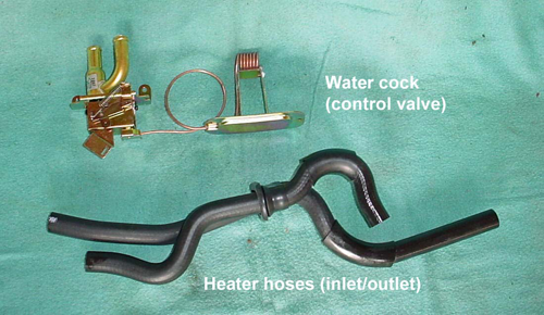
Figure 3-1 New Heater Hoses and Manual Control Water Cock
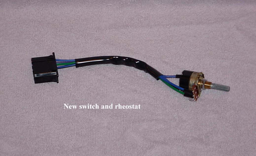
Figure 3-2 New Combination Switch/Rheostat
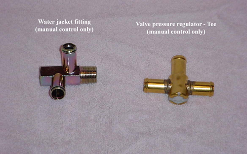
Figure 3-3 New Fittings at Engine Block
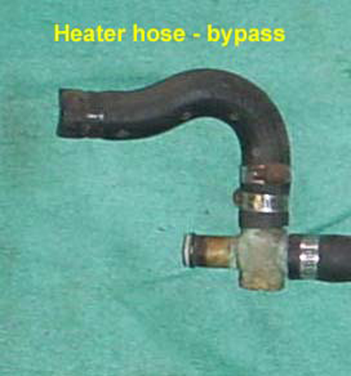
Figure 3-4 Heat Hose – Bypass (for Manual Control only)
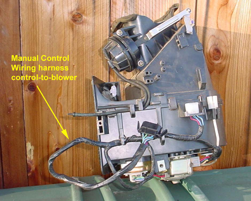
Figure 3-5
Wiring Harness
Currently Attached to Blower Unit
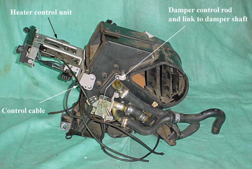
Figure 3-6
Manual Heater Unit Showing Various Parts
Section 4 Parts to be Removed From Automatic Climate Control
Refer to Figures 4-1 through 4-4 for details showing which parts can be removed during this modification.
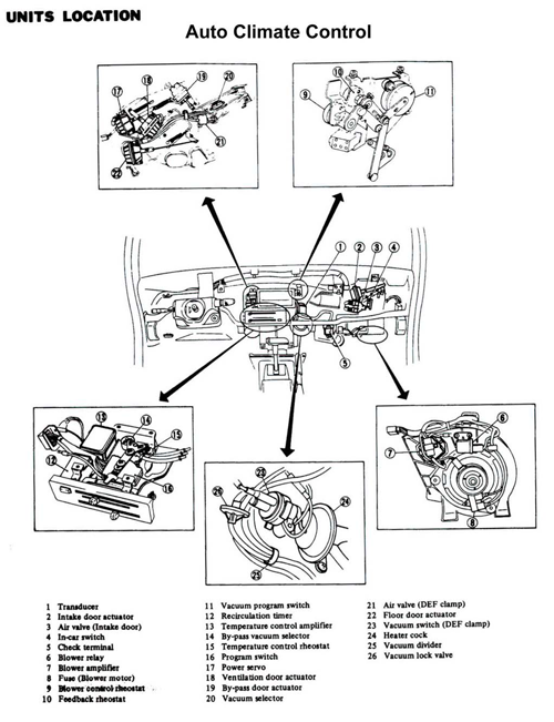
Figure 4-1 Parts To Be Removed
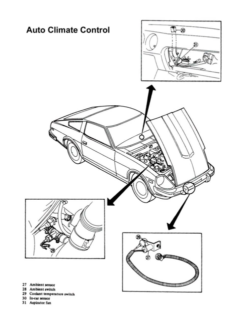
Figure 4-2 Parts To Be Removed
From Figure 4-1 the following parts need to be removed:
Part No.
>Description Remove or not and further explanation 1
Transducer
Remove – refer to Figure 4-3 for better view
2
Intake door actuator
Do not remove – part of blower assembly
3
Air valve – intake door
Do not remove – replace vacuum hoses
4
In-car switch
Remove
5
Check terminal
Removed as part of wiring harness
6
Blower relay
Do not remove – part of blower assembly
7
Blower amplifier
Remove – to be replaced by Manual unit
8
Fuse (blower motor)
Do not remove
9
Blower control rheostat
Remove entire unit consisting of 9, 10, and 11 – refer to Figure 4-4 for better view and detail.
10
Feedback rheostat
Remove entire unit consisting of 9, 10, and 11 – refer to Figure 4-4 for better view and detail.
11
Vacuum program switch
Remove entire unit consisting of 9, 10, and 11 – refer to Figure 4-4 for better view and detail.
12
Recirculation timer
Remove all parts 12 through 16 as unit
13
Temperature control amplifier
Remove all parts 12 through 16 as unit
14
Bypass vacuum selector
Remove all parts 12 through 16 as unit
15
Temperature control rheostat
Remove all parts 12 through 16 as unit
16
Program switch
Remove all parts 12 through 16 as unit
17
Power servo
Remove as not necessary – See Section 5.2
18
Ventilation door actuator
Do not remove
19
Bypass door actuator
Do not remove
20
Vacuum selector
Removed as part of control unit 12-16 above
21
Air valve (DEF clamp)
Remove
22
Floor door actuator
Do not remove
23
Vacuum switch (DEF clamp)
Remove
24
Heater cock
Remove and replace with manual unit – See Section 5.3
25
Vacuum divider
Remove
26
Vacuum lock valve
Remove
From Figure 4-2 the following parts need to be removed:
Part No.
Description
Remove or not and further explanation
27
Ambient sensor
Remove or leave in place - unimportant
28
Ambient switch
Remove or leave in place - unimportant
29
Coolant temperature switch
Remove – See Section 6 for heater hose configuration
30
In-car sensor
Remove or leave – cut wires
31
Aspirator fan
Remove or leave – cut wires
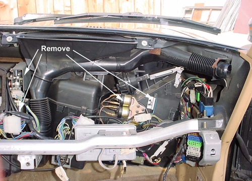
Figure 4-3 Some Actual Parts to be Removed
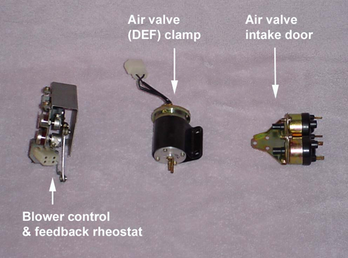
Figure 4-4 Actual Auto Control Parts After Removal
Section 5 Heater Removal and Modifications
5.1 Heater Unit Removal
The component requiring the most modifications is the heater unit. All of the auto control hardware must be removed from the heater unit and the air mix door actuation mechanism must be modified. In addition, the heater water cock must be replaced and all the ventilation doors or dampers must have their vacuum lines rerouted.
By looking at the components in place after the dash is removed (refer to Figure 2-1, Dash Removal) you can see that the dash support bar impedes the removal. The best solution is to remove the support bar or strut which supports the dash and sits directly in front of the heater, A/C unit evaporator and blower.
1. Unbolt the dash support bar from both ends and unbolt the steering column from the bar plus the support bracket on the left side, just next to the steering column. Leave one bolt on the right end since it drops down after all bolts are removed.
2. Drop the bar from the right support and the left side can be lifted from it support. Remove the bar from the car. Remember the removal sequence for re-installation.
3. Carefully unbolt the defrost ducts from just underneath the windshield. They are held in place by one screw and the upper tabs are underneath the nylon nuts for the top of the dash. Label all parts left or right but some are already marked at fabrication.
4. Now the heater unit can be removed. First make sure the coolant system was drained. Then loosen the hose clamps at the heater hoses, located between the heater unit and A/C evaporator. An easier way to remove these hoses would be to cut them just at the outside of the firewall (in the engine compartment).
5. Disconnect the two vacuum hoses coming from the firewall. Disconnect the two vacuum hoses at the inlet damper (located at the top of the blower). Most of the original vacuum hoses have plastic connectors at some point along the length, which makes it easier to connect and disconnect than at the damper body itself. Save all old plastic connectors from the old vacuum tubing (especially any “T” connectors).
6. Unbolt the heater unit. Four bolts, two at the firewall and two on the transmission tunnel.
7. Disconnect the necessary wiring harnesses and label each.
8. Carefully pull the heater unit out and away from the firewall, pulling the heater hoses through the firewall.
9. With the heater unit out of the car, remove the auto control parts that are discussed in Section 4. In particular, remove the auto blower control unit from the right side (parts 9, 10 and 11 of Figure 4-1).
10. Remove the entire control unit from the front of the heater unit. (Parts 12 through 16 of Figure 4-1). Save all vacuum hoses and fittings, you will need some of the fittings later. The control unit is attached by two screws on the left side and two on the right side.
11. Section 5.2 will discuss the air-mix door modification. Section 5.3 will install the manual water cock and control rod for the air-mix door.
12. Install the entire control unit of a manual control heater unit. Refer to Figure 5.3-1 below for the position of the control unit.
5.2 Air-Mix Door Modifications
The air-mix door of the auto control is moved by a vacuum driven power servo or cylinder. This power servo must be removed from the left side of the heater unit, and replaced with the manual control rod on the right side.
Refer to Figure 5.2-1 for the left side of the heater unit showing the power servo and indicating which parts are to be removed. Save all the vacuum tubing and fittings. There are only two screws holding servo in place and one small screw holding the arm on to the door shaft.
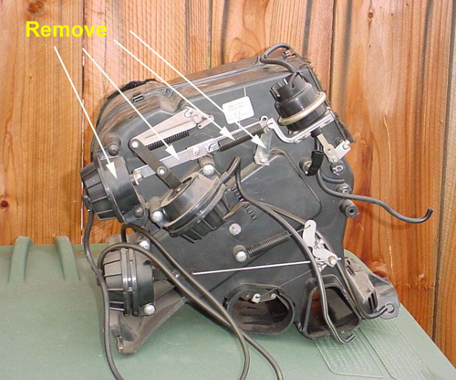
Figure 5.2-1 Power Servo and Accessory Parts Removal
Next, switch to the right side of heater unit and remove the auto control water cock valve. Refer to Figure 5.2-2 for this valve.
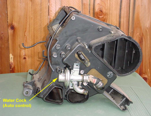
Figure 5.2-2 Auto Control Water Cock
Note the small length of heater hose from the water cock to the inlet of the heater core. This heater hose must be replaced with new hose and connected into place on the manual control water cock. See next section.
5.3 Water Cock Replacement
1. Before installing the new manual water cock, test and observe the travel of the actuating arm and how the valve opens and closes. Note and mark the position of the valve arm when closed by blowing into the valve at various travel positions and observing when closed. This position will be important when adjusting the control cable later (Section 5.4).
2. Install the new manual control water cock as shown in Figure 5.3-1.
3. Install the short heater hose on the water valve as shown and secure with hose clamps.
4. Route the heat coil of the water cock, to the back of the heater unit. The heat coil is a coiled copper tube as shown in Figure 3-1.
5. Remove the small cover plate over the access hole at the back of the heater unit.
6. Install the heat coil into the back of the unit and secure with the two screws.
7. Install the control rod from the water cock to the shaft of the air-mix door as shown in Figure 5.3-2.
8. Install the control cable from the control unit to the water cock. Refer to Figures 5.3-1, 5.3-2 and 5.3-3 for details.
9. Adjustment of the control rod and control cable will be performed in the next section (Section 5.4).
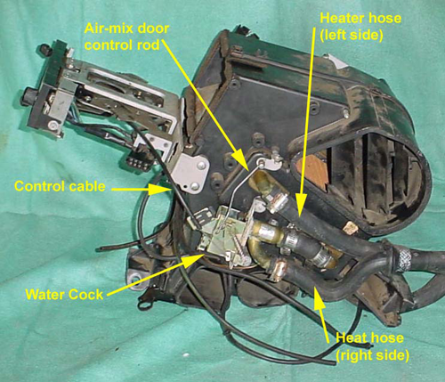
Figure 5.3-1 Water Valve or Water Cock for Manual Control
Note Manual Control Unit Has Been Installed on Front of Heater Unit
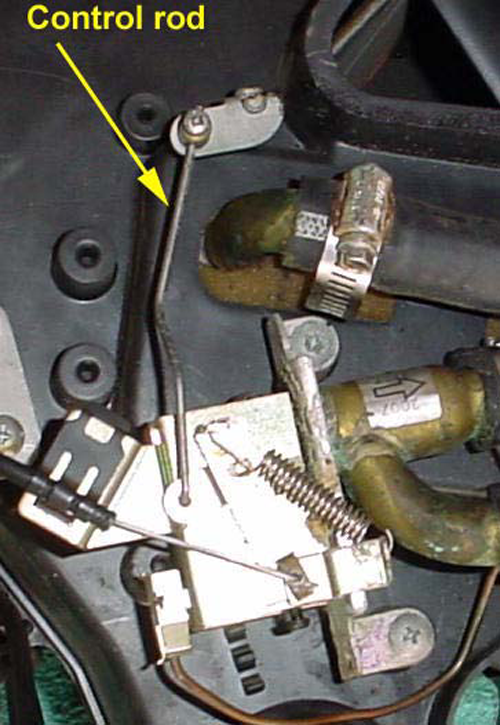
Figure 5.3-2
Air-Mix Door Control Rod
From Water Cock
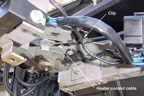
Figure 5.3-3
Control Cable at Control Unit
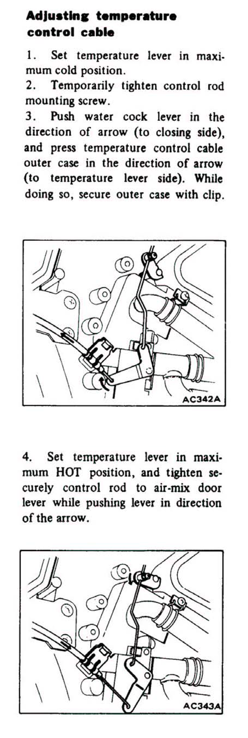
5.4 Water Cock Control Cable Adjustment
The control cable leading from the control unit to the water cock, is now adjusted per the instructions in the shop manual as attached in this procedure.
Section 6 Engine Modifications
1. The heater hose connector at the very back end of the engine (just above the #6 spark plug) must be replaced. It is advantageous to also remove the fuel injector blower from the right side (spark plug side) of the block, in order to have room to replace the heater hoses. Also, it may be advantageous to remove the spark plug wires (after numbering) and the vacuum lines routed to the intake manifold.
2. The auto control fitting (single hose) must be replaced with the manual control (two hose) fitting.
3. Remove the old fitting and replace with the new fitting (use Teflon tape on the pipe thread). The orientation of the fitting is as shown below in figure 6-1.
4. The water temperature switch in the auto control heater hose line is replaced (at about the same position), with the valve pressure regulator tee.
5. Replace the remaining heater hose and connect as shown in the Figures 6-1 and 6-2 below.
6. Route the new heater hoses through the firewall and connect as shown in Figure 6-1.
Note: The right hand heater hose (viewed from the passenger seat) leads to the “two-hose” fitting just above the #6 spark plug while the left hand heater hose goes to the valve-pressure regulator tee. See Figures 6-1 and 6-2.
7. Leave the fuel injector coolant blower out until the engine has been restarted and checked for leaks.
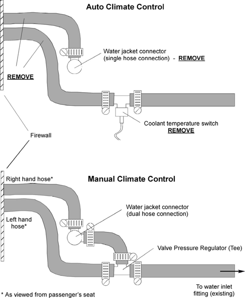
Figure 6-1
Side View of Engine Block Showing Heater Hose Arrangement
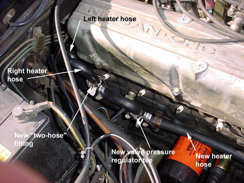
Figure 6-2
New heater Hoses and Fittings
Section 7 Blower Unit and Vacuum Tank Modifications, Vacuum Hose Routing
7.1 Blower Unit Modification
The Nissan parts fiche shows a separate part number for the blower amplifier in comparing the Auto with the Manual control models. The Auto control amplifier must be replaced with the Manual control amplifier. Just unbolt the Auto unit and replace with the Manual unit. Be careful and don’t pull down too hard on the amp unit, it is somewhat fragile. The blower relay and fuse unit are identical for both types of models. Only the wiring harness needs to be replaced.
1. Remove all the auto control parts per Section 4. Also remove the wiring harness leading from the blower over to the heater control unit. The wires directly attached to the fuse holder, the amplifier, the relay and the blower unit remain in place and are connected to the manual control wiring harness.
2. Replace the two vacuum lines leading to the servo for the air intake door, located at the top of the blower unit.
7.2 Vacuum Tank Modification
1. The vacuum tank is located at the right front side of the engine. It has two magnet or solenoid valves attached to the backside and a number of vacuum lines leaving the tank at the backside. Refer to the shop manual if unsure of its location.
2. There is no need to modify the vacuum tank. The auto. control has two lines leading from the tank through the firewall, while the manual only has one line. Just seal off the one line that is not needed. This will be the line coming from the tank body itself. Note the second vacuum line leads from the black-capped magnet (or solenoid) valve. This second line is the only source of vacuum needed for the manual control.
3. Replace this vacuum hose with “new material”. These vacuum hoses in the engine compartment get hard and brittle over time and will crack, thereby losing vacuum.
4. Remove the second vacuum line and plug or cap at some point, since it will not be needed. Plug the hole in the firewall. You can opt not to pull the old, second vacuum line out through the firewall since this will leave a small hole in the firewall. Just seal or clamp shut the vacuum line so it doesn’t leak. Whatever you do with this second line it would be advantageous to use new hose also.
7.3 Vacuum Hose Routing
1. Your should now only have one new vacuum hose leading from the vacuum tank to the dash area.
2. Before installing the heater unit, replace the vacuum hoses leading from the vacuum selector, located on the bottom of the control unit, to the various servos and to the vacuum control knob or switch which will be mounted on the driver’s side, lower dash panel.
Refer to the vacuum diagram for exact connections. See Figure 7.3-1 below.
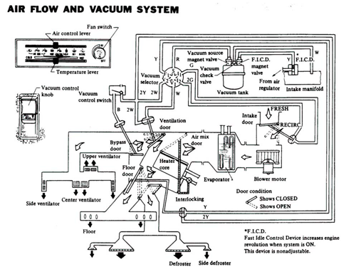
Figure 7.3-1 Vacuum Diagram for Manual Control Heat and A/C
Section 8 Installation, Testing and Checkout
8.1 Installation
1. With the heater unit modified with the new water cock and the vacuum hoses routed to the various servo valves, the unit is ready to be re-installed in the car.
2. Before re-installation, place new foam insulation strips on the sealing edge of the front heater vent and the side leading to the A/C evaporator. See Figure 8-1 for details. The type of foam insulation to use is about 1/2” wide and 3/8” thick with self-sticking adhesive on one side.
3. Place the heater up against the firewall and bolt into place with the four bolts. Make sure the unit mates correctly with the A/C evaporator.
4. Connect the vacuum hose from the vacuum tank to the correct position on the vacuum selector (position marked “S”).
5. Spray silicon lubricant on the heater hose fittings at the side of the heater unit and slip on the heater hoses. Clamp into place.
6. Connect the last two vacuum hoses from the intake valve (top of blower) to the heater control unit. vacuum selector (positions I 1 and I 2 )
7. Connect the new wiring harness from the control unit to the blower.
8.2 Testing and Checkout
With the rebuilt heater unit in place and the heater hoses replaced:
1. Fill the radiator.
2. Connect the battery negative terminal.
3. Before re-installing the dash support bar and the dash, the engine will be started and the heater, blower and AC tested.
4. Start the engine and allow the coolant to heat up.
5. Check for leaks at all replaced heater hoses and fittings.
6. With the engine running, run the heater and A/C through all the various positions and check the doors for proper operation. Check for hot air at the floor ducts (exit at the heater unit). Check for hot air at the defrost ducts. Check for cold air while in A/C. Make sure the blower speed can be adjusted with the rheostat. Refer to Figures 8-2 and 8.3 for assistance.
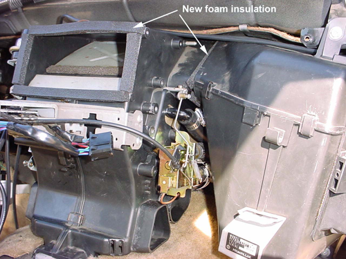
Figure 8-1 New Foam Insulation Added
8.3 Completion
1. Important -- Disconnect the negative battery lead for re-installation.
2. Re-install the fuel injector blower at the right side of the engine.
3. Re-install the dash support beam in the reverse order as the removal.
4. Re-install the dashboard in the reverse order as removal.
5. Re-install the steering wheel shaft covers and steering wheel.
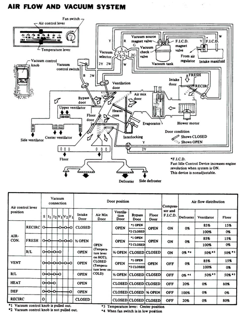
Figure 8-2 Checkout and Testing
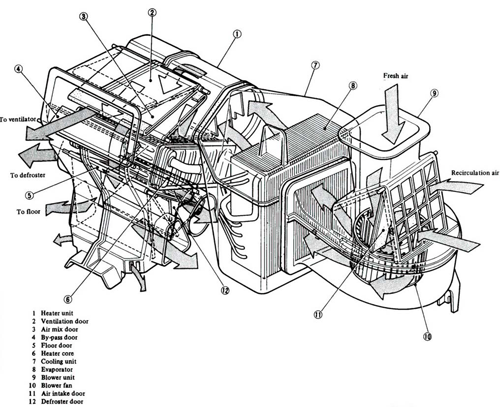
Figure 8-3 Heater, A/C Unit and Blower