
S130 Refreshing Your Air Flow Meter
Warning: This may seem like a simple and straightforward procedure, however, there is always the possibility of error, and you're responsible any damage you cause by attempting this procedure yourself. It is fairly easy, and can make a world of difference in your car's driveability, but your results may vary. Some Air Flow Meters may not need any recalibration or adjustment whatsoever, but this tutorial shows what would be done if you were paying to have your AFM rebuilt.
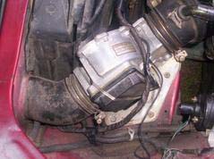
Step 1: Locate your AFM. If you don't know where your AFM is, chances are you shouldn't even be attempting this procedure, but if you insist, it's located in the left front side of your engine compartment, and looks something like this:
Step 2: Clean Your AFM. This may not be the most fun, but your AFM is more than likely more than 2 decades old and chances are it hasn't been so much as wiped out in that entire time. That would be a rather significant layer of buildup in there, and no doubt has to be adversely affecting your performance. There is a small plastic piece protruding from the side - this is your Air Temperature Sensor; be sure it's clean and free of buildup, but be sure to refrain from damaging it. A cloth or paper towel should be sufficient for cleaning the internals of your AFM, but if more is needed, brake cleaner is useful for its lack of greasy film and quick evaporation. Be sure to wipe any excess cleaner away, regardless.
3: Cleaning Your Connectors. This sounds like something silly, but it could possibly be one of the most important parts of the entire procedure. A dirty or corroded connection could very well be the cause of your AFM problems, and many a person has needlessly opened up their AFM when all they needed was to clean their connections. This may or may not take a lot of time, it varies depending on how horribly corroded and dirty your connectors are.
- You're going to want to have the following supplies:
- Electrical Cleaner
- Small Flathead Screwdriver (One from an eyeglass repair kit will do.)
- Dielectric Grease
The first thing you need to do is locate the connector on the underside of the AFM. If you removed the AFM from the car, the harness connector should be easy to find. Spray down the connectors on both the AFM and the harness with just enough cleaner to soften the corrosion. Let the cleaner soak for a moment, then grab your flathead screwdriver and start scraping that corrosion off of the connectors. Give another squirt of the cleaner and let it dry, then use a paper towel or cloth to clean off any remaining debris. Set the dielectric grease aside - you'll need it later.
Step 4: Opening the AFM. Now comes the "fun" part: getting the AFM case open. It's not insanely difficult, just avoid gouging yourself while trying to open it. You can use a flathead screwdriver, a razor blade, or whatever else you find suitable for the task. The lid is held in place by a silicone sealant, which must be separated from the lid by inserting the tip of your screwdriver or razor blase and slide it firmly along the perimeter of the case, making sure you're cutting through the sealant and not just riding on top of it. Once you've made a couple passes around just pry the lid off with the screwdriver. This part can be stubborn but it WILL come off. These lids aren't delicate so don’t be afraid to pry, just don’t overdo it. When in doubt, cut around the edge to make sure you got all of the sealant.
Step 5: Examine Your AFM. The insides of your Air Flow Meter should look something similar to this image below. Click the image for a much larger view. (429k JPG)
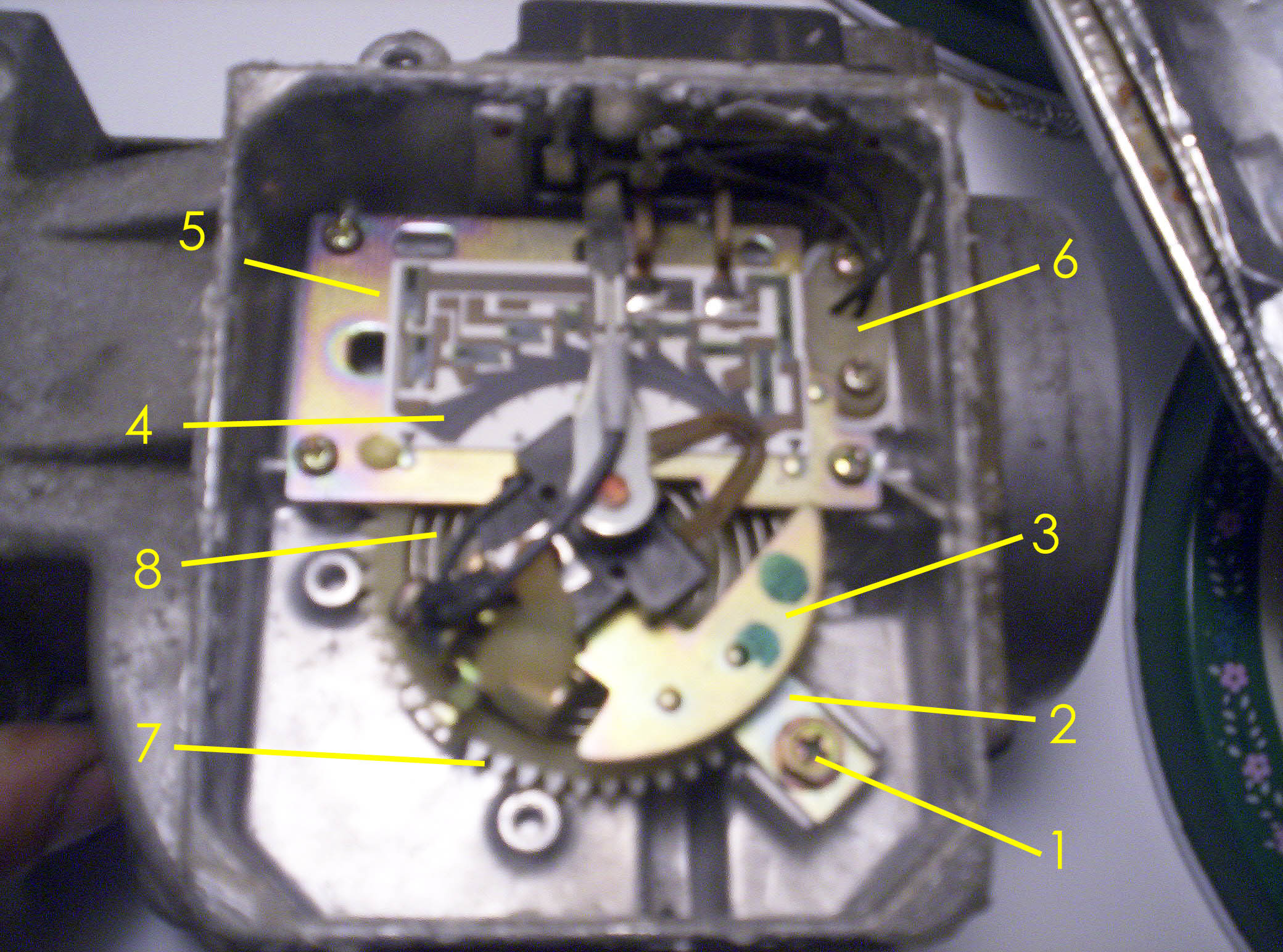
- These parts are identified as follows:
- Set Screw for Spring Tension Retainer
- Spring Tension Retainer
- Flapper Door Counterweight
- Carbon Track
- Circuit Plate
- Air Temperature Sensor
- Spring Tension Adjuster Cog
- Flapper Door Tension Spring
Step 6: Adjusting The Carbon Track. If you examine your Carbon Track, you can see that there are probably two grooves in it where the swiper arm passes over it and wears down into that carbon over time. Basically, the Carbon Track is a resistance field, and the swiper arm slides along it and sends a signal to your ECU based on its position and resistance to determine the position of the flapper door. As time goes by, the swiper arm has created those parallel grooves you see running along its path, and they can cause it to lose contact with the carbon track in some manner, and the resistance will be changed, seinding a faulty signal to your ECU and negatively affecting your driveability. What we need to do is give that swiper arm a fresh piece of carbon track to move upon so the resistance is back to normal, and we will do this by moving the circuit plate slightly - even 1mm is enough to make a difference.
You’ll need to loosen the 3 screws that hold the circuit plate in place, however be sure to only loosen them slightly. You don’t want the plate moving around on its own, and you don’t need to remove them. Now we want to push the plate up towards the casing, but DO NOT move the plate side to side or the swiper arm can come off the track at some point. You only want to move the plate just enough so that the swiper arm contacts are no longer traveling in the grooves. Less than 1 mm is adequate. Now tighten the screws and push the swiper arm through its swing radius and make sure that it at no point intersects the old grooves or comes off the black carbon track. This is important. If it does either at any point then driveability will suffer. Once you're sure then double check that the screws are tight and this step is finished.
NOTE: If for some reason you can't move the plate far enough up, try moving it down. If that still doesn’t give you enough adjustability then you can use a file and enlarge the screw holes. Just make sure the carbon track is properly aligned side to side. That is far more important than top to bottom. Now it's time to reinstall the AFM back into the car. You can either finish off after that or keep on with the following procedures if you so choose.
Now is the time to make use of that dielectric grease we've had handy since we started this process. Seal up your electrical connectors well in order to keep moisture out to prevent corrosion and keep your AFM working properly. If you don't own an air/fuel ratio gauge, then I wouldn’t recommend carrying on with the following procedures as their purpose is to adjust the air fuel mixture. If you're into trial and error or have the strange ability to sense air/fuel ratios then by all means carry on. As always, performing the following procedures is done at your own risk.
Step 7: Adjusting the Idle Mixture. The Idle Mixture Adjustment Screw is located on the lower side of the AFM near the inlet, as seen in the picture below.
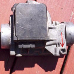
Not all AFM have this screw, however. All non turbo models should, but some turbo models may not. If you don't have this screw, you can obviously skip this step.
What the screw does is meter the amount of air that is allowed to bypass the AFM. Since this amount of air is such a small amount, it really only affects the air/fuel ratio at idle. This works on the principle that while the flapper door signal is telling the ECU that only 'X' amount of air is getting in, the mixture screw is allowing more air to bypass. This in turns leans or enriches the mixture depending on screw position. To adjust the mixture all's you need is a flathead screwdriver, but you really should have an air/fuel gauge hooked up to the car. The screw is supposed to have a plug over it but over the last 20 + years it's bound to not be there. But if it is just pop it out. Now, with the flathead screwdriver you simply turn the screw in the direction needed to correct your mixture:
- Clockwise = richer
- Counterclockwise = leaner
The reason is that as you turn the screw clockwise, you close the air passage and let less air through and the mixture becomes richer. If you turn the screw counterclockwise start to draw the screw out and this opens the air bypass and allows more air through which leans the mixture out.
Step 8: Flapper Door Tension Adjustment. This mod has a couple of functions, but if done without the aid of an air/fuel gauge can affect your car’s performance in a negative manner. The reason I originally attempted this mod was to lessen the force necessary to open the flapper door, which would mean less resistance for incoming air. Unfortunately I was thinking of the impact this would have performance. The spring tension is precisely calibrated (or at least it was at one point), and messing with the spring tension will alter the air/fuel mixture. The only point at which the air/fuel mixture isn't affected is at wide-open throttle. The flapper door can only open so far so at wide-open throttle, it doesn't really matter what the spring tension is.
- Here's the breakdown on what the adjusments do and why:
- Lightening Spring Tension: This will richen the mixture. This happens because as you lighten the tension on the spring, less and less air is required to open the flapper door a given amount. Meanwhile the ECU is calibrated to think that the spring is still at its OEM settings and so will still think that more air is actually flowing in. This will cause the ECU to still dump in its calculated amount of fuel, but since less air is actually coming in this causes the mixture to richen.
- Strengthening Spring Tension: This does the opposite. It leans the mixture, and it does it because it now takes more air pressure to open the door to a given width. The ECU reacts the same way as if lightening, relying on its factory programmed settings, only now it leans the mixture out by adding less fuel. (NOTE: DO NOT, under any circumstance lean your mixture out below the factory setting unless you have an air/fuel mixture meter hooked up. This can cause serious engine damage. A rich mixture will do nothing more than cause driveability issues and maybe foul your plugs. A lean condition can destroy your engine.)
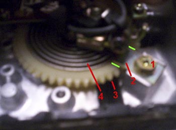
Now that you understand the principles and the risks, here are the steps for this procedure. You're going to want to have a Phillips screwdriver and a permanent marker handy. The first thing you need to do is make two reference marks with your permanent marker. If you look at the picture below, you'll see two green lines on either side of the Tension Spring Retainer. This is where you should make your reference marks. This way you'll know how much adjustment you've made and always be able to come back to your original settings. If you skip this step, you may end up sorry.
Now you'll need your screwdriver. Break the screw loose but don’t loosen it yet (some have glue holding them in place). Now secure the tension spring cog in place. You can use a flathead screwdriver, but I just use my fingers. What ever you do, just don’t let it go or it'll spin until the spring is completely slack – NOT good. Now with that secure, loosen the retainer screw enough to the point where the cog can be turned. If you want to lighten the pressure then the cog will do all the work. Just let it turn itself. If you want to tighten the spring tension then you need to work against the spring pressure. Then just tighten the screw down and check your results. Check you air/fuel ratio at different RPM's. Once you have satisfactory readings you are finished and you can now seal up your AFM. You're finished. Enjoy your new-found driveability.